emergency stop x1
Keith Rowell Design
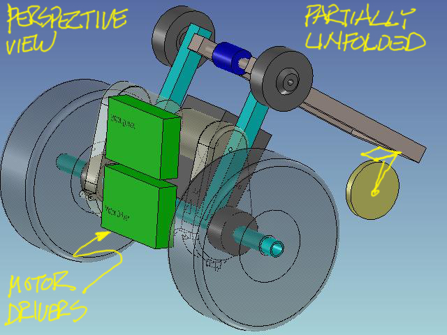
We've got lots of new parts this week and bold new designs.
Lots of parts are comming this week, forgive me if I miss any;
New Parts
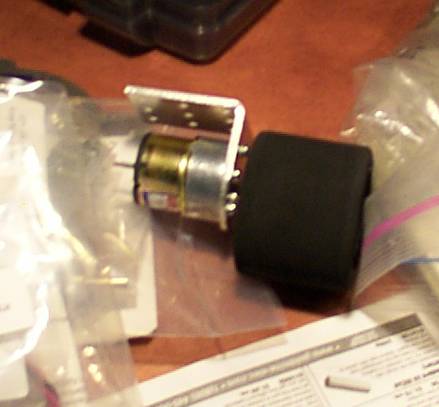
Emergency Stop Button Jay Cross
Fuse Holders x2 Mike Lynch
12vBatt x1 Mike Lynch
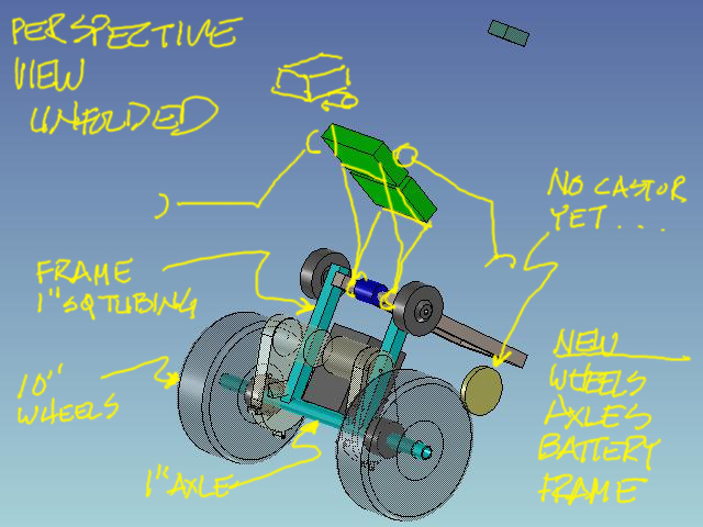
1"SqTubing Mike Lynch
from hand truck, includes removable handle
1" round axle stock Mike Lynch
3/8" round axle stock Mike Lynch
retainer caps for same
10"wheels Mike Lynch
4" wheels Mike Lynch
more?
Clint Bridges also gave me the Solutions Cubed box. It's got nice stuff, but I haven't drawn it up yet. I'll report on that next week as time allows. Looks like we are going to wind up with more than enough stuff to build two bots, maybe a Kangaroo and it's Joey?
Still Needed
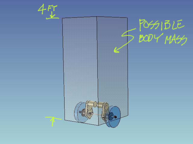
Castor wheel
Sheet Stock for frame and mounting of circuitboards and such, perforated would be ideal
Sheet plexi Stock for shrouds, mounts, etc.
MCU
Sensors
ideas!
Progress Feels Good
It's been great to see the participation and intrest in this mascot project. I could "re-design" forever, it's in my nature, but I know some people want to get started as soon as possible. I believe Mike has plans to start the hub modification soon and needs a lathe for part of that process. I will have access to one in January. Anyone else anxious?
Next week I will have the "Solutions3" inventory online and maybe some of you guys could look into what parts you would like to incorporate into this bot, and what kind of #2 bot you might want to undertake from those parts.
Also, these CAD files are very convertible. I can export the model in almost any CAD format. Anyone who wants a copy, just email me:
rowell@mindspring.com. I would host the cad format files in a central location if it were convenient, and I've looked into it in the past. That collaboration tool hasn't been made as convenient or cheap as the "blog" format so far. I'll bark if that changes.
Just one more thing. Some of these used parts are skuffed up and scratched. If anyone has experience with this new "plastic" spray paint, or has an opinion about colors and "styling", please comment. I can imagine using the dark gray and pale yellow of the AHRC logo. Keeps the theme going. For more color and style ideas, it's very usefull to email a photo showing the finnish you like. I can "pick" these from the photo and use them directly in the rendering program. Seen any cool machinery lately that you'ld like to emulate? Is this going to be industrial grunge like the terminator? shinny like C3PO? or something fancy like the "lost in space second generation"?