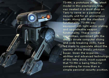
StarWars robot design is somewhat "Dog-Like"
Keith Rowell Design
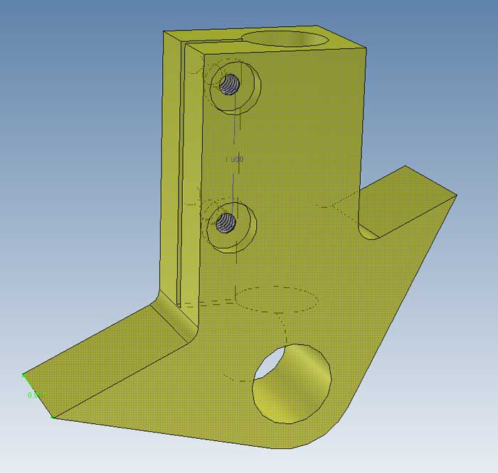
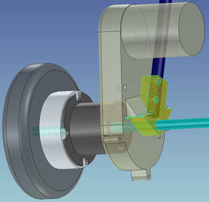
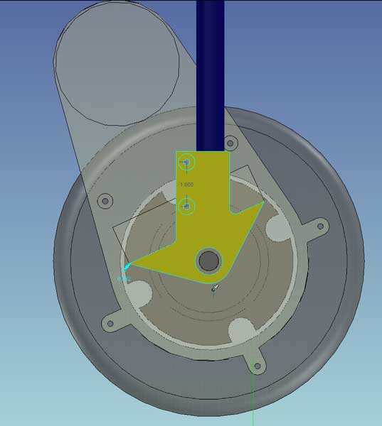
The motor mount design was discussed. The virtues of using an added "plate" to attach the bracket to the gearbox was weighed against keeping the "boss stop" method that the gearbox originally used. The crux of the discussion revolves around wheather any weight is transferred to the gearbox. The general consensus is that the gearbox should "float" and that all the weight should be transferred to the wheel through the axle.
2. Articulated Frame
After discussing the modifications to the "umbrella folding baby stroller" and how to add shrouds and motors to drive articulation on such a frame, it was suggested that we abandon that frame and make one from scratch that suits our needs exactly. This sidesteps the difficulties of making the pseudo appropriate frame fit our critera, while serving as good reference material for a new design.I'll post some sketches showing some of these ideas applied to our project. I look forward to your feedback.
3. Paint
It appears that the wax (applied too soon after painting) caused the paint to crack. I didn't get many other comments about the silver painted gearboxes. Please provide some input as to aesthetic styles that you would like to explore for the mascot.
4. Reference material
I've included some references here that might provide some inspiration for our mascot's design.
Hoberman was a student of Buckminster Fuller's geodesic dome design principles, and has since created fantastic articulated shapes such as the Hoberman sphere that you may have seen in toy stores. These are amazingly complex expanding structures, definitely the kind of design I would consider to be "showing off" worthy. Here are a couple of his newest mechanical odities.
http://hoberman.com/fold/Switchkick/switchkick.htm
http://hoberman.com/fold/Braintwist/braintwist.htm
http://hoberman.com/fold/assoc/projects.htm#
http://hoberman.com/fold/sightings/clinton.jpg
Some standard off the shelf mechanical shapes:
http://www.hobbyengineering.com/SectionFR.html
http://www.beijingthc.com/conveyor_chain/carbon_steel_one_piece_chains.htm
http://www.partserver.de/frame.asp?firm=duffnorton&language=english
Mechanical linkages simulations
sphynx is an incredible spherical 4 bar linkage simulator, as is Synthetica. Try them out!
http://synthetica.eng.uci.edu:16080/~mccarthy/Synthetica1.0/Synthetica.htm
http://gram.eng.uci.edu/~mccarthy/SphinxPC/Sphinx.html
http://www.keypress.com/sketchpad/javasketchpad/about.php
http://www.brockeng.com/mechanism/index.htm
http://math2.math.nthu.edu.tw/jcchuan/java-sketchpad/jsp.html
http://www.enchantedlearning.com/physics/machines/Levers.shtml
Fictitious Designs
http://www.colinmackenzie.net/robots/amee/
http://mullenmj.astromech.net/T3M4Droid.htm
Real Designs