The link below shows a forum and file sharing site set up for online collaboration in the Mascot project. Try it out and provide your opinion please.
http://www.thinkcycle.org/tc-space/tspace?tspace_id=65434
Tuesday, October 31, 2006
Wednesday, December 07, 2005
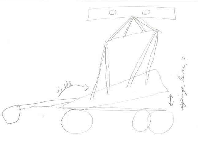
Telescoping Lift
telescoping lift
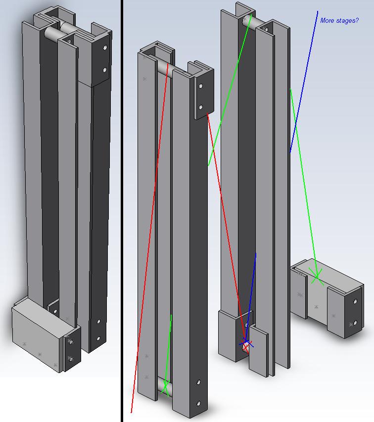
Here is a Paint-hacked drawing of the telescoping lift I was talking about. This one uses 1/2" aluminum angle and goes to 14".
I suppose it can be scaled up and modified to elimiate the sliding metal contact, or even some real bearing pads will suffice. It can probably be done with 1" aluminum square tube from Home Depot.
Actuated using cables that tie each stage(in this case there's only one and a half) to the one before it, so a big winch can be used to raise it.
It's more work than drawer slides(which can probably be used in conjunction with the design) but I think it will be much lighter for a given size/height, and no "screwy" components.
Does anyone know what this is actually called? I have seen it on several ceiling service lifts and a few forklifts. Most of them actually did use anchored cables instead of nested cylinders.
From: Team Test Bot
Wednesday, November 23, 2005
New Frame
new frame
Well after a long "quiet" period in the mascot activities, we've begun to make some new changes to the design. On the previous RBNO, Mike Lynch brought in some new castors and a couple were added to the CAD files. (you can see one of them here)
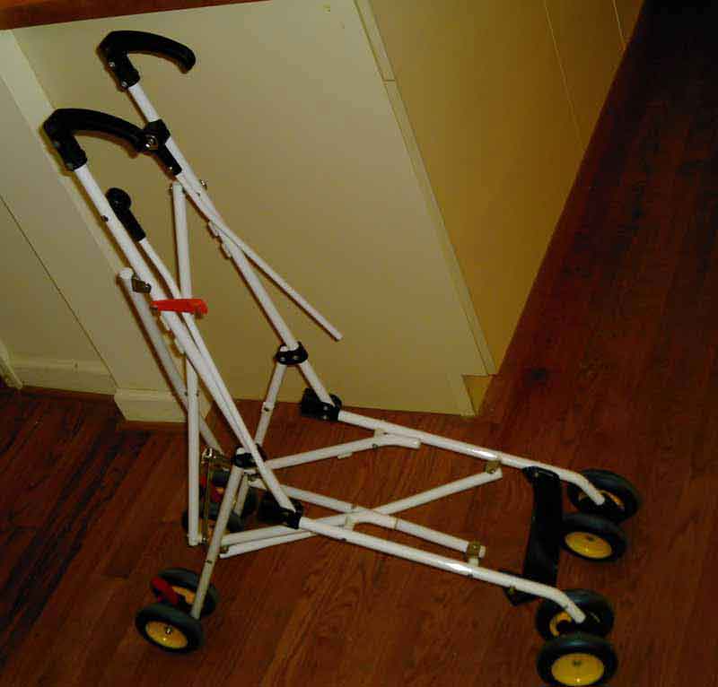
Previous attempts to intrest the group in using an "umbrella" baby stroller for the frame, failed. Although this design was light and "ready made", perhaps it was percieved as, well, baby stuff.
So we've got a new frame design, based on the previous design, using 1" square steel tubing and flat plate. The motors were re-oriented to take advantage of the boss cast into the motors (that prevent them from turning around the shaft). The location of the castor wheels were widened for stability. I've included PDF drawings of the frame parts here:
The units are in decimal inches and disregard the 3 decimal places.
gusset
frame01
frame02
frame03
If you're not familiar with machinists tapes, a decimal inch is divided into 10ths instead of the archictural 1/4qtrs, 1/8ths, and 16ths. The first decimal place is 10ths of an inch, the second is 100ths, the 3rd 1000ths. You can ignore the 3rd decimal place for our purposes.
Slide Actuation for Height

accuride 3601 - 28
During the discussion about gaining height and adding "transformer" style unfolding, Dale Heatherington mentioned using drawer slides. I managed to find sample slides from Accuride, they donated model 3601 which is one of their heaviest slides. Two of them will hold 273 lbs and move smothly. I propose using just one of them for the mascot as they are so heavy and strong. There are other offers of slides in the wings and I hope they are better for our purpose, because of the 3601's weight. See the specs , 3601, web
The extended length is 57" and the closed length is 28".
Base with 3601 slide

base with slide
This image shows the base with the slide extended. It reaches 69" tall. All of the extension would not be available after adding a ball screw type extender so this example is exaggerated in height by 4 to 6". Still, five plus feet is an impressive height. And that doesn't include a head.
3601 Slide Closed

3601 slide closed
The size of the closed bot with the new slide bothered me some. The bounding box shows the total envelope as 9x28x22. Would someone measure their trunk and report if this is too big?
There's also a problem with the distance between the motors. The slide wont pass between them when closing. The interference is about 1/4". I'll have to double check the models with the actual motors to see if I left myself any spare. As I recall, the motor connectors are in the rear area, and wiring space will be needed there. We might be able to widen the frame an inch to accomodate this problem. As you will recall, we set the width to be 24" in order to pass through the smallest doors. Standard doors are 28" with 26" being a small door and 32" a large door for moving furniture through and such.
Max Headroom
maximum space for head
When the bounding box is added to the extended slide, and shortened to fit around the motors when closed, the image above shows the results. There is space for torso bracing. I'll address that after feedback on this current design comes in. My biggest concern about this design is it's weight. I coudn't say at this point if it's going to be closer to 50lbs or 100lbs. If we change to aluminum, we'll be alot happier with the weight, but welding aluminum is a very different animal, and I don't have a volunteer. The slide is steel and very heavy. I'm not aware of any aluminum slides. Perhaps we should follow Dale and Eric's leads and start using more wood and plastic. It wouldn't be a disaster if we wound up with a heavy bot. We can always make another one. We should avoid this error however if we can. Please comment and I'll adjust the design according to your feedback.

Monday, July 25, 2005
"I don't have a pen"
Finally I have a chance to pick back up on the Mascot Project. I'll start where we left off by publishing the sketch exercise we did last.
Amid scoffs of "it will never work" and " I don't have a pen", we did a brainstorming design exercise where individuals draw their concepts on paper and the paper was passed around to others to draw on, adding their own doodles to the "collective" design. Only a couple of sketches had any combinations of more than one design. Congratulations to those who were able to relinquish their sketch to another's brutal hand. I know it's tough for logical engineer types to "cast about" for inspiration, so congratulations to everyone for participating.
The "logic" of the exercise is to bounce ideas around quickly, building on what another person sees in your idea that you may not. It's also a spin-off on the "two heads are better than one" concept.
I've presented the sketches below and commented on each briefly. Please add your explanation if you are the author and I've missed an important point.
I'll incorporate the ideas, that are new, from this exercise into the CAD model next month. Remember the design criteria...The 4 main design objectives for a "club mascot" should be:
- 1. Light and easy to transport
- 2. Big for visual impact
- 3. Flamboyant, showing off, technological cleverness to be proud of
- 4. Cheap, cheap,cheap
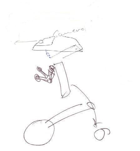
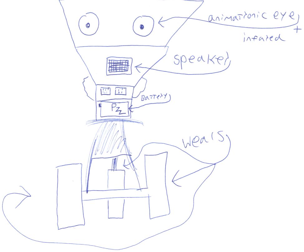
I took the liberty to combine some of the sketch elements from a couple of different sketches in these first few, sort of in the spirit of the exercise. This one is much like the original design but with arms, head, and camera, added from other sketches. I find the head particulary "modern".
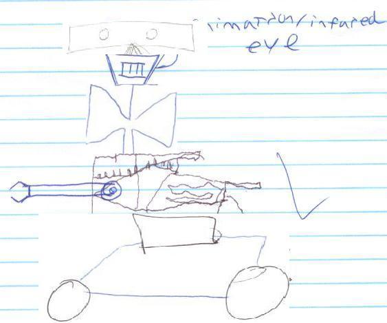


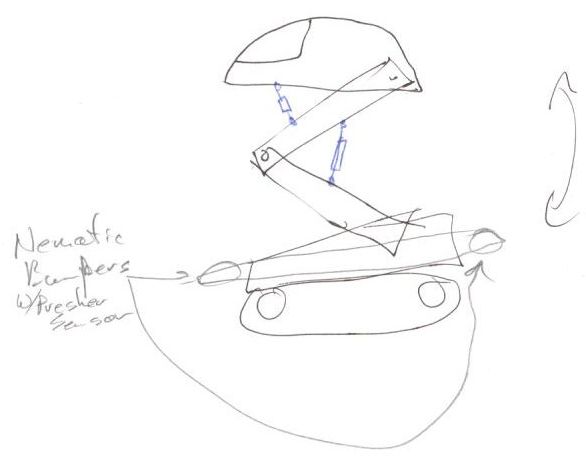
This sketch had two contributors. This is a fine example of sharing ideas via the community sketch concept. I have entertained the scissor-lift idea before, but I've never seen the folding / right angle / idea before (in blue). It sort of reminds me of retractable landing gear on a plane. I can see this being used for dolly wheels and such.

On first glance, this one can seem to be bullet shaped, but the cone is a collection of leader lines pointing to motor locations. It can look like a wheeled cart with humanoid articulated bot (light blue). Or if you include the leaders and turn the face 180deg., the dark blue cart looks like a left foot and the bullet becomes the face. Right brain optical tricks and accidents can become unique designs.


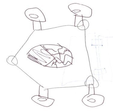
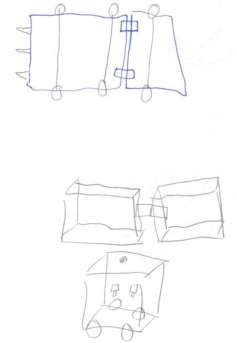
This one seems to have a tubular framework and folding outrigger wheels. Reminds me of the "shrimp" locomotion bot. I've been looking again at this platform lately because of it's ability to climb stairs with wheels.
This member clearly wants a battlebot mascot. I believe the intent to do a demonstration robot would preclude destroying it at every presentation, but I could be wrong. Battlebots attract attention. It's possible to fall asleep when "johnny" robot is calibrating his sonars. No so when "etek" is ripping a printer apart. What message do we want to send?

Sunday, February 27, 2005
February Meeting Update
The mascot section of the February Club meeting brought some good feedback.
1. Motor Mount
The in-ordinate ammount of play in the joints of the stroler frame is another source of dissatisfaction and new designs need to take this into account.
Many design mechanisms were suggested:
1. Motor Mount
The motor mount design was discussed. The virtues of using an added "plate" to attach the bracket to the gearbox was weighed against keeping the "boss stop" method that the gearbox originally used. The crux of the discussion revolves around wheather any weight is transferred to the gearbox. The general consensus is that the gearbox should "float" and that all the weight should be transferred to the wheel through the axle.
2. Articulated Frame
After discussing the modifications to the "umbrella folding baby stroller" and how to add shrouds and motors to drive articulation on such a frame, it was suggested that we abandon that frame and make one from scratch that suits our needs exactly. This sidesteps the difficulties of making the pseudo appropriate frame fit our critera, while serving as good reference material for a new design.The in-ordinate ammount of play in the joints of the stroler frame is another source of dissatisfaction and new designs need to take this into account.
Many design mechanisms were suggested:
- rack and pinion
- drawer slider mechs
- scissor lift
- ball screw
I'll post some sketches showing some of these ideas applied to our project. I look forward to your feedback.
3. Paint
It appears that the wax (applied too soon after painting) caused the paint to crack. I didn't get many other comments about the silver painted gearboxes. Please provide some input as to aesthetic styles that you would like to explore for the mascot.
4. Reference material
I've included some references here that might provide some inspiration for our mascot's design.
Hoberman was a student of Buckminster Fuller's geodesic dome design principles, and has since created fantastic articulated shapes such as the Hoberman sphere that you may have seen in toy stores. These are amazingly complex expanding structures, definitely the kind of design I would consider to be "showing off" worthy. Here are a couple of his newest mechanical odities.
http://hoberman.com/fold/Switchkick/switchkick.htm
http://hoberman.com/fold/Braintwist/braintwist.htm
http://hoberman.com/fold/assoc/projects.htm#
http://hoberman.com/fold/sightings/clinton.jpg
Some standard off the shelf mechanical shapes:
http://www.hobbyengineering.com/SectionFR.html
http://www.beijingthc.com/conveyor_chain/carbon_steel_one_piece_chains.htm
http://www.partserver.de/frame.asp?firm=duffnorton&language=english
Mechanical linkages simulations
sphynx is an incredible spherical 4 bar linkage simulator, as is Synthetica. Try them out!
http://synthetica.eng.uci.edu:16080/~mccarthy/Synthetica1.0/Synthetica.htm
http://gram.eng.uci.edu/~mccarthy/SphinxPC/Sphinx.html
http://www.keypress.com/sketchpad/javasketchpad/about.php
http://www.brockeng.com/mechanism/index.htm
http://math2.math.nthu.edu.tw/jcchuan/java-sketchpad/jsp.html
http://www.enchantedlearning.com/physics/machines/Levers.shtml
Fictitious Designs
http://www.colinmackenzie.net/robots/amee/
http://mullenmj.astromech.net/T3M4Droid.htm
Real Designs
Sunday, February 06, 2005
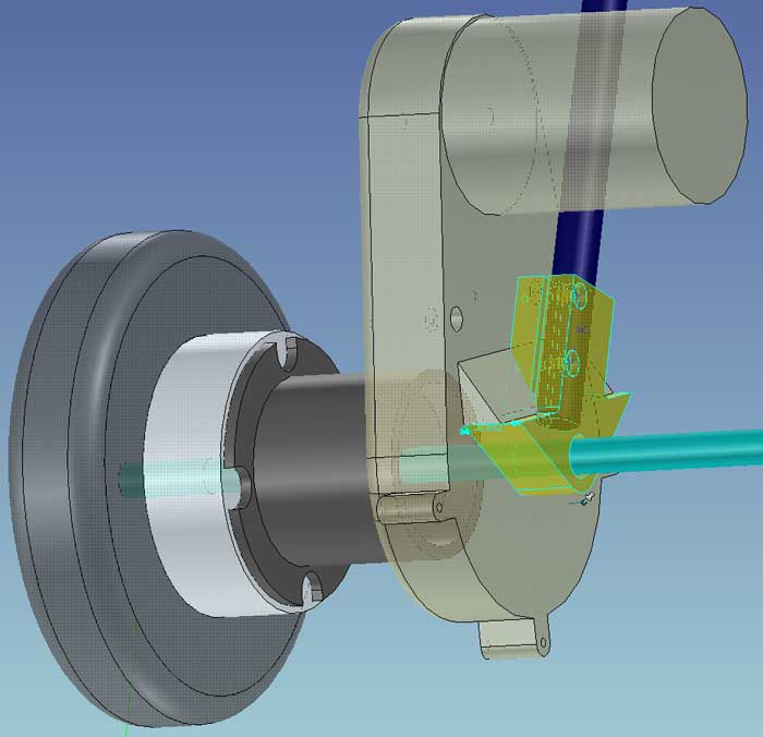
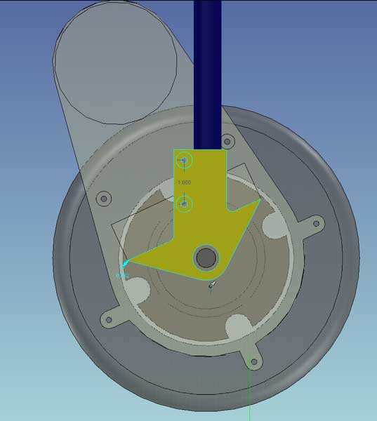
GearBox / Motor Mount Design for Folding Frame
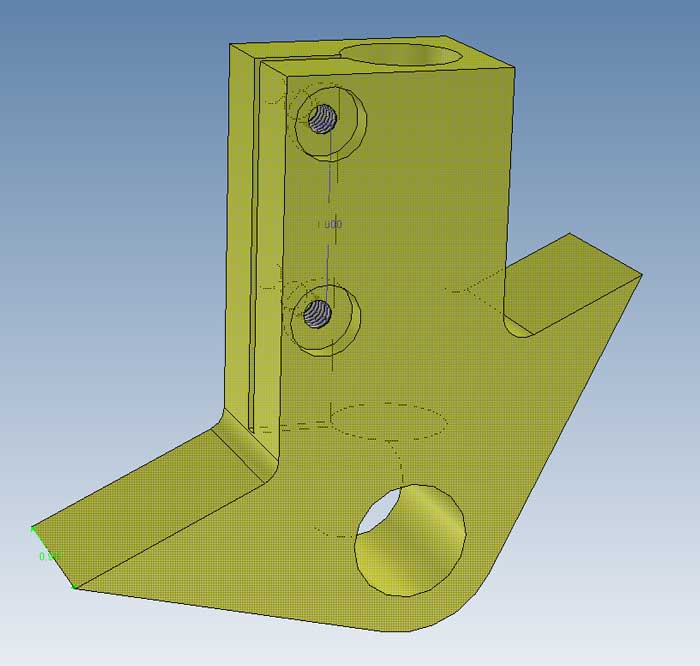
motor mount
Keith Rowell Design
I've worked up some motor mounts based on the discussion in the January meeting. (held in Feb.) These are to mount the gearboxes onto the folding frame.
I was able to modify the folding frame to maintain it's width when closed, as per the meeting comments. It appears that the bottom "x"scissor brace controls closed width, and the vertical "x" scissor brace controls the angle of the vertical frame when fully open. I drilled out the rivetes and moved the connect points and achieved a configuration per saturday's comments. In the current configuration, when the motors are added the full width is 26.7" wide. That's with the frame's outer rails at 12.75". In order to bring the total width down to 24", the folding frame needs to be modified further to have a total width of around 10".
I don't have a camera handy today, I will post those photos when available.
motor mount front
Keith Rowell Design
The basics of this motor mount design are that the top is a clamp that compresses the frame's down tube. The weight of the bot is carried on the axle that distributes it out to the wheel, passing through the gearbox and coupler. The awkward angle on the motor mount corresponds to a boss on the gearbox, keeping it stationary under torque. It doesn't carry any weight.
motor mount side
Keith Rowell Design
We of course are looking for volunteers to build this part. There are two of them, identical except for the screw holes which should be mirror copy on the two parts. I have atatched a pdf of the part drawing on the listbot. Contact me if you need a copy...
Monday, January 24, 2005
Casters

Casters
Keith Rowell Design
I found these cool double wheeled casters in a thrift store for $6. Any of you with children will recognise the stroller. The caster wheels are about 4" and very stable.

Subscribe to:
Posts (Atom)